Pier Design
Written By: Stephen Macmillan
Email: smacmillan@qvalent.com
Introduction
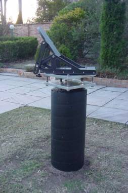
After spending six months levelling a tripod then performing a 20 � 40 minute drift alignment every time I wanted to image, I decided I needed a more permanent set-up. Where I live is heavily tree studded. The only clear view is in the pool area. This spot provides me with reasonable north and south views. After some discussion with my �non-astronomy inclined� wife, an observatory in the pool area was not an option. A pier became a reasonable compromise. I then spent a considerable amount of time scanning the Internet for pier designs.
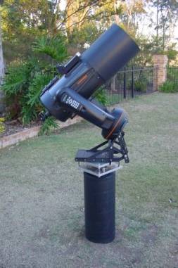
After some research, I decided on a 12" diameter concrete pier using a two-plate system to mount my wedge on. The pier is designed to suite my Nexstar 11 GPS and Celestron heavy duty wedge, ant with some modification of the top plate holes, will suite any SCT wedge or equatorial head. As the Nexstar 11 GPS has an internal compass I steered away from any designs involving mild steel due to the effect it could have on the compass pointing.
Equipment
I am not a handy person. Cutting a piece of timber straight is a challenge, but with a bit of assistance from friends and the local hardware store, building a pier is a fairly straightforward exercise.
Parts List
| Description | Qty |
|---|---|
| Aluminium Plate 12" x 12" x 3/4" | 2 |
| Sonotube 12" x 48" long | 1 |
| 2x4's 8 feet long | 3 |
| Stainless all-thread rod, 3ft x 3/4" | 1 |
| Stainless nuts 3/4" | 9 |
| Stainless washers 3/4" | 9 |
| Stainless all-thread rod, 3ft x 1/2" | 1 |
| Stainless nuts 1/2" | 16 |
| Stainless Washers 1/2" | 16 |
| Rebar 3/8" x 4ft | 4 |
| Stainless bolt, washer & nut 3" x 5/16 | 1 |
| Rebar 3/8" x 2ft | 4 |
| Wood plate 12" x 12" x ¾" | 1 |
| Wood Screws 3½" | 10 |
| Cement 40Kg bag | 4 |
| Mild steel hex nuts | 6 |
| Mild steel plate 2"x2" | 3 |
| Sand & Gravel 3/4 cubic metre | 1 |
All of the above parts were sourced from a local metal dealer, hardware store or concreting supply store. While stainless steel was used for all the threaded rods, washers and nuts, the plates where made of aluminium rather than stainless steel. Aluminium is considerably cheaper than stainless, and Aluminium is a lot easier to file if any of your drilled holes don�t quite line up.
Digging The Hole
Once you decide where to place the pier its time to start digging. It�s always wise to check that there are no pipes or power cables under ground. As you can see from these photos, my pier is close to the pool, so I was careful when digging to ensure I didn�t hit any piping. Luckily, none was present.
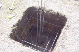
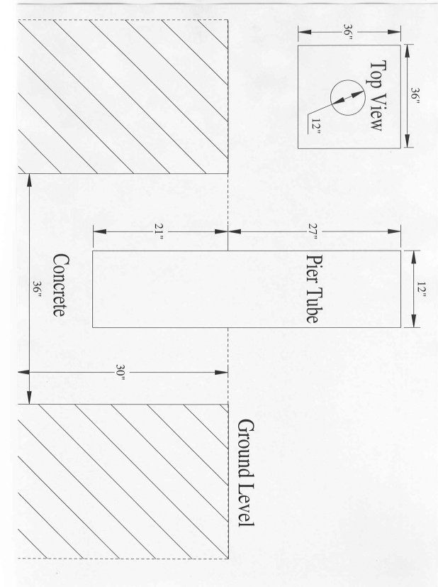
I was planning a 3� x 3� x 3� hole as this seemed like a good size to support the 12" diameter pier. When I got down to 2 ½� I hit sandstone, nothing like having a solid base, so I stopped there. The next step was to create a rebar cage. This gives the concrete strength. The cage consisted of 3/8" rebar formed into a 2� cube and four x 4� pieces of rebar in the centre to provide strength for the column itself. I used wire to form up the rebar cube. Its good if you can avoid the rebar from touching the dirt and seal it in concrete. This will prevent it from rusting. Refer to Figure 12, Hole Size.
Forming Up
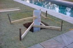
After the rebar is in place its time to form up the pier column. I ended up purchasing a plastic tube used to make cement columns from a scaffolding and formwork supplier. The tube constructed in such a way that it can be pealed away once the concrete is set. As a general rule, the diameter of the pier should be at least the same as the diameter of the scope. In my case the scope diameter is 11 inches so I went for a 12" pier diameter. I wanted to be able to view sitting down, so I made the tube rise 27" above ground level. This combined with the 6" of the dual plates and the 15" of the wedge, gives and overall height of 48". Adjust the pier height to suite your needs. You need to suspend the tube in the centre of the hole with at least 6" clearance between the bottom of the tube and the base of the hole. This is to allow enough concrete to form a solid base under the tube.
Use the 2x4�s as formwork to suspend the tube. This can be done by forming a triangle of formwork at ground level and two pieces as side braces. Now use the 3 ½" wood screws to screw the timber into the sonotube. It�s important to get the tube plumb. Its handy if the ground around the pier hole is level as this helps get the tube plumb. Now use wooden pegs to secure the formwork in place and to stop the sonotube from moving when you pour the concrete.
Pouring the Concrete
Its very important that you don�t make the concrete too wet. Keep the amount of water you add to a minimum. If the concrete is sloppy you will have alot water in the hole. This will cause the concrete to drop or move as it dries. I used a sand and gravel mix. The gravel size was approx ½ - ¾". This was purchased from a local landscaping supplier. With this mix I used a six parts sand/gravel to one part off white cement ratio. If you buy the sand and gravel separately, try a four-part sand, two-part gravel to one part cement. Add the water slowly until the mixture is just wet. Shovel the mixture into the hole instead of pouring it straight out of the barrow. Pouring it in from a barrow could knock the sonotube out of alignment. Start by filling up between the outside of the sonotube and pier walls. If you want to replace the grass, fill up to about 3" from the top of the hole. This leaves enough room for grass and topsoil. Now shovel the concrete into the sonotube. As you are shovelling in the concrete tap the sides with a rubber mallet. This will help pack the concrete down and remove any air bubbles. Fill with concrete to the top of the tube.
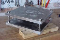
The mounting system
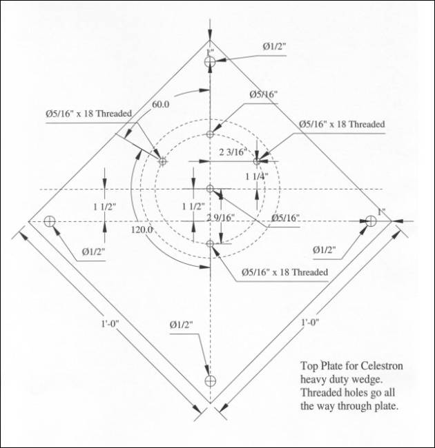
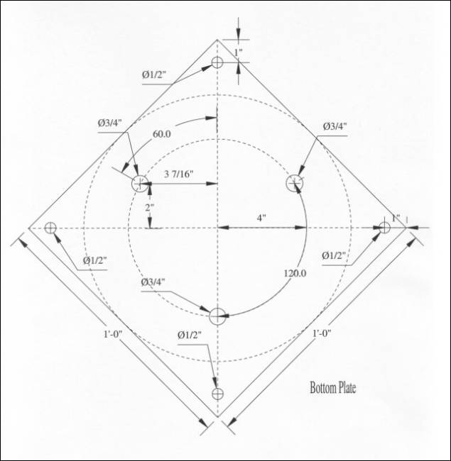
To support the wedge I used a two- plate system. This consists of two 12" x 12" x ¾" aluminium plates held together by four pieces of ½" stainless steel threaded rod and stainless steel nuts and washers. Refer to Figure 9, Top Plate and Figure 10, Bottom Plate for the CAD drawing of these plates. To mount this to the pier I used three 12" x ¾" stainless steel threaded rods embedded in the concrete. All of these materials are available from a local steel supplier. Trying to cut stainless steel is not fun. Ask the steel supplier to cut it for you. A number of pier designs I read about on the �net bent the bottom of the threaded rod before embedding it in to the cement. Trying to bend ¾" stainless steel is also not on my top ten fun ways to spend a Saturday. When I spoke to the steel supplier and explained I wanted to embed the three 12" sections of ¾" threaded rod into the concrete, he suggested I use a bolt and plate technique. This involves screwing a ¾" mild steel nut, a 2" square mild steel plate with a ¾" hole in the centre of it then another ¾" nut underneath. Now lock these together with spanners. This is a standard way used in the building industry. The 2" square plates with ¾" holes can be purchased at a steel or formwork supplier. The threaded rod / nut / plate / nut is the same technique used to separate the two aluminium plates that hold the wedge. I searched the Internet for the hole and location dimensions for the Celestron heavy-duty wedge without any luck. So I measured them myself and drew up the attached cad drawings. I then gave the drawing, the two aluminium plates and the wedge to a friend of mine who is a workshop foreman. He then drilled and tapped the holes in the plates as per my plans, but also rechecked the dimensions against the actual wedge to confirm that my drawings were accurate. The plans attached should be sufficient for any metal shop to drill and tap the plates for you.
Creating the Template
� To make up the template that will be used to embed the three x 12" x ¾" threaded rods into the concrete, cut a piece of wood the same size as the bottom aluminium bottom plate and about the same thickness. Place the aluminium plate over the top of the wooden plate and clamp together. Now use a ¾" spade bit to drill the three holes in the wood using the Aluminium plate as a guide template.
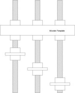
I elected to have 4" of thread rod exposed from the top of the pier and 8" embedded in the pier. Use stainless steel nuts and washers to lock the threaded rod at the correct height on wooden template. The top nut will be removed, but the bottom nut will be embedded in the concrete. The top of this nut will be exposed to the atmosphere, so use stainless. Vary the nut and plate anchoring system at different heights on the bottom 8" of threaded rod. As these will be covered in concrete mild steel can be used. They will also be far enough away from the scope not to affect its internal compass. Now draw a line going between the north and south corners of the template. This line will be used to assist in pointing the template at the pole.
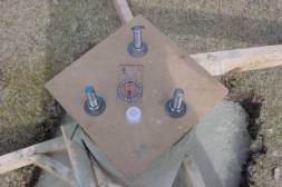
Inserting the template
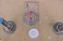
Once you have filled up the column with concrete and smoothed it off, its time to insert the template. This is critical, especially if you are using a wedge. A wedge only has a limited amount of movement in azimuth, so you want to ensure that the template is pointing towards the north or south celestial pole, depending on what part of the world you are in, in my case, the south celestial pole. Now take the template and push it into the concrete working it down to ensure that there are no gaps. Now place compass on the line. Set the compass to take the local magnetic variation into account for your area. In my case it is 12 degrees. Adjust the template so the line you drew on it is parallel with the direction the compass is pointing. You now have the template pointing towards the true pole. Refer to Figure 6, Template, if you are in the northern hemisphere the top bolt (in relation to the photo) should be pointing towards true north. In the southern hemisphere, point it towards true south. One last important point, place a bubble level on the template and make sure it is level, otherwise the threaded rods will not be pointing straight up. You may need to place a small wedge between the top of the sonotube and template to level it.
Drying
Let the concrete set for a week before removing the formwork and sonotube. If you are planning on painting the column, wait four weeks before applying any paint. This will ensure all moisture has been removed from the column and will not lift the paint.
Mounting the Scope
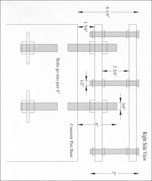
Once the concrete has set the template can be removed. Now the mounting plates and wedge can be assembled and bolted to the threaded rods. I used four 5"x ½ stainless steel rods to separate the two plates. In all instances I used stainless steel washers with the nuts. Refer to Figure 11, Right Side View, Also Showing Plates Assembled and Threaded Rod Anchors, to see how the plates are assembled together. If anything does not quite line up, filing aluminium is very easy. Now level the wedge. To do this, adjust the nuts on the bottom plate until the top plate and wedge are level. I would suggest using a bubble level instead of the level built into the wedge. I found the accuracy of the level in the wedge leaves a bit to be desired. Now mount the scope and perform a drift alignment. Once you are happy with the alignment, lock down all the screws and nuts. Finished!
Final Tip
If you are mounting an equatorial head on the pier you should have no issues with vibration. Unfortunately, the fork arms on wedge mounted SCT�s are infamous for inducing vibration. This only occurs when you tap the fork arms or turn the focus knob, no vibration should be evident during tracking. Case in point is that Celestron ships vibration suppression pads with the Nexstar 11 GPS. Meade also sells a version of these pads. If you have any vibration issues with your fork mounted SCT there are a couple of things you can do:
Look closely at the photos of the Celestron heavy-duty wedge. I have undone the side allen screws and azimuth adjuster and moved the base plate forward to the front set of side holes. I then cut a wooden block to size and placed it in the back of the wedge to extend the shelf. This helps reduce flexure in the wedge. Thanks to Robert Berta for this tip.
Obtain a thin sheet (⅛") of sorbothane. This is a special material used to dampen engine vibration. It is also the same material used in the Celestron vibration suppression pads. Starizona (www.starizona.com) sell a sorbothane suppression pad, which consists of the sorbothane sheet and a thin metal plate with pre drilled holes to suite the Celestron wedge. Place the sorbothane sheet and plate between the pier top plate and wedge. Tapping the fork arms now dampens out in approx 2 seconds.