Here are a few tips that people might find helpful...
Subwoofer Calibration: BFD
If you graph subwoofer frequency response vs db level from say 25Hz to 100Hz you should get a reasonably flat response in theory. Unfortunately due to the low frequency waves interacting with your room, you get a graph that looks more like a rollercoaster! These peaks and valleys play havoc with your sub. When you calibrate it using test tones you will naturally adjust it for its loudest point which would be a peak. You will then find that your sub has no impact or sounds 'boomy' due to the valleys. Using two subs can help by canceling out some of the peaks and valleys, but it does solve the issue. I can be particularly tricky if your sub(s) is in a fixed position (like me) and can not be moved around the room.
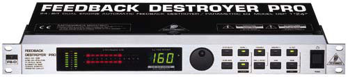
Enter the Behringer Feedback Destroyer Pro (DSP1124P), this is the silver bullet of subwoofer calibration. It is a piece of professional audio gear that is used to kill feedback at rock concerts. Its other function is a parametric equaliser. This device allows you to cut peaks and boast valleys to produce a flat subwoofer response. It can control two subs at once. The best part is that this device sells for approx $185 AUD! I won't go into its operation as an outstanding guide has already been written by Sonnie parker and is available here.
While a flat response is good, what you really want the BFD to give you is a 'house curve', this is a gradual sloping line that drops about 7db from 20Hz to 80hz. This is based around the theory that the human ear is less sensitive to low frequency sounds, so by having a slightly higher level at lower frequencies, the sound 'appears' flat across the board. To read more about this just do a search on the net for "house curve". Attached here is the spreadsheet I used to program a "house curve" into my BFD.
So, what does it sound like with all the peaks and valleys removed and a 'house curve' programmed in? You get deep powerful tight bass that you more feel than hear at moderate listening levels, basically just live the movies!
 Subs only - Blue
line before BFD, Pink line with BFD
Subs only - Blue
line before BFD, Pink line with BFD
 Subs +
Mains (80Hz crossover) - Blue line before BFD, Pink line with
BFD
Subs +
Mains (80Hz crossover) - Blue line before BFD, Pink line with
BFD
Subwoofer Calibration: SMS-1
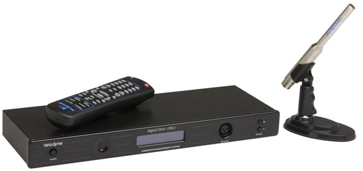
I've been using a Behringer feedback Destroyer (BFD) for 4 years to EQ my subs. The Velodyne SMS-1 replaced this. While both units achieve similar results, using the SMS-1 with its on screen display certainly makes it easy to EQ your sub(s).
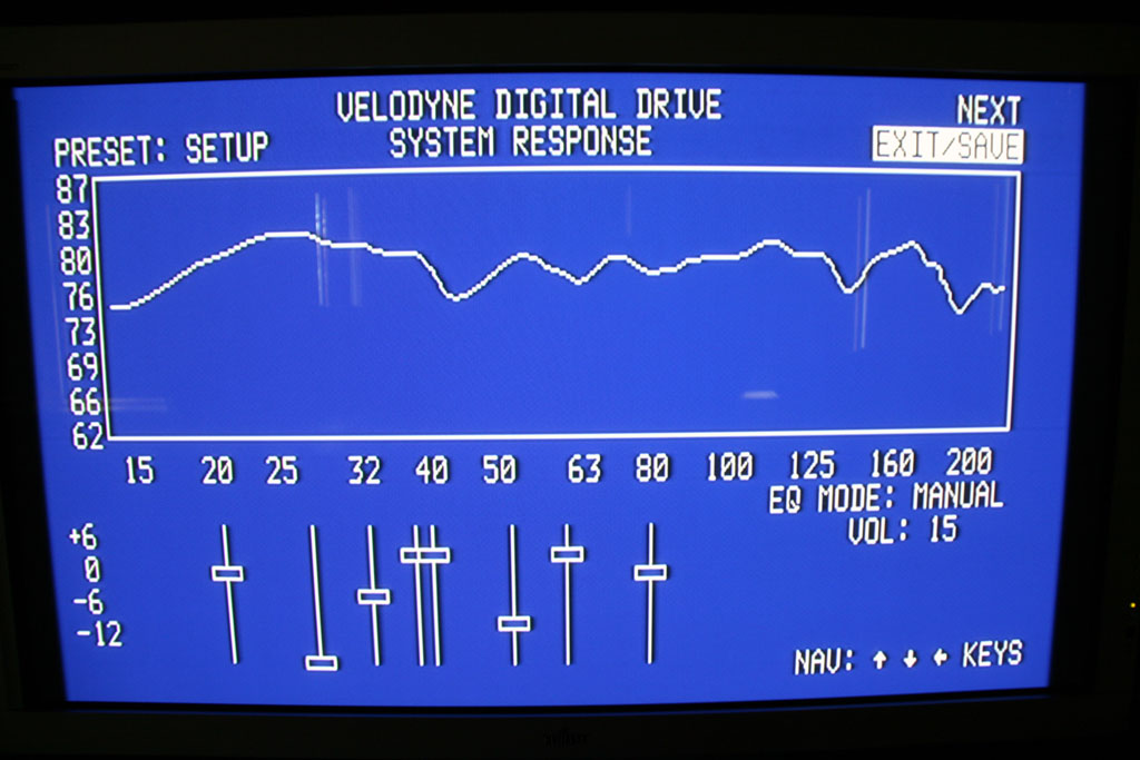
Using the BFD and a laptop running REW, EQing your subs is a semi manual process. You run the tones and observe the graph. You then manually enter cuts or boosts into the BFD and repeat the process. Note that you can get a cable to allow REW to program the BFD. I didn't have one of these. With the SMS-1 it is all real-time. As you are making the adjustments with the remote it is being displayed on your TV screen. As my subs are located in cabinets (wife acceptance factor) getting to the volume and phase controls is difficult. The SMS-1 allows you to adjust these (including polarity) through its user interface without getting behind the subs. This is a big help when you are trying to get a smooth cross over between your subs and mains.
The SMS-1 also adds a great deal of flexibility to allow different EQ modes, for movies and music through its various presets. You can all defeat all EQ though one button press on the remote. EQ default is also possible through the front panel of the BFD, but does not offer the same level of flexibility with phase, EQ curves and volume and assigning these to various presets. One last added advantage of the SMS-1 over the BFD was a very small bit of hum that was introduced by the BFD. You could only hear this if you put your head near the subs or speakers. Groundloops are a know issue with BFD's. Now with the SMS-1 both speakers and subs are dead silent.
The below graph for my two subs (2 x SVS SB13-Plus's) and mains was achieved in around 30 minutes once I had the SMS-1 installed. I like have a 'house curve' (a slight slope from lower frequencies to the sub cut off around 80Hz) instead of a flat line. A 'house curve' tends to give more sub impact at lower listening levels. To achieve a similar results with a BFD would take a couple of hours.
The SMS-1 does cost more that the BFD by a considerable margin, but it greatly simplifies the EQ process. If you can pick up a second hand SMS-1 at a good price i would recommend it. Saying that, EQing your subs with a BFD does give you a good understanding of room acoustics and is enjoyable if you like �tinkering�.
Whether you choose the SMS-1 or BFD, the outcome of both these units is tight bass that is smooth without the boominess. Watching (actually feeling) the scorpion scene from Transformers with EQ�d subs always brings a smile to my face!
Sound Pressure Meter
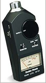
One of the most useful devices you can purchase is a sound level meter. This allows you to measure sound level in decibels. The most common one on the market is the Radio Shack meter and can be picked up at a electronics store for around $30. To get a good speaker or subwoofer calibration, its mandatory to have one of these.
Some useful fully calibration DVD's to try out are Digital Video Essentials (PAL edition in my case), Avia and the THX Optimiser which in included on a number of DVD's such as Monster's Inc or Finding Nemo. This discs allow you to calibrate both audio and video, to achieve the best out of your setup.
Ground Loops
if you plug in a new piece of HT gear and a hum starts resonating from your speakers more that likely you have a ground loop in your system. I have no formal electrical training so take this advise with a gain of salt...
A ground loop is usually generated because you have equipment connected to circuits with different ground potentials. This can typically occur through your antenna cable. For example in my case my family room is all on it own dedicated circuit so I should be free of ground loops or so I thought...
I purchased a HT tuner card for my PC with is located in my study on a different circuit. When I installed an antenna socket in the study the power supply in the PC set up a ground loop (different circuit with a different ground potential) via the antenna cabling that caused the speakers in the family room to hum! When I unplugged the antenna from the PC in the study the hum from the speakers in the family room instantly stopped.
If you want to read all about ground loops I would suggest this link
Two Capacitor Isolator construction
Ok, so how do you get rid of them. In my case I build a simple two capacitor isolator. All the parts can be purchased from Jaycar for less than $10. The following information is all copyright of ELH communications Pty.
This circuit is a simple isolator for TV and Radio antenna connection. This circuit passes radio frequency signals nicely, but does not pass significantly 50 Hz signals, so the ground loop is eliminated. The circuit can be easily built into antenna connector or to a small box. I would recommend to use small metal box, where you connect one of the antenna connectors to the metal box and isolate other connector from box. Metal box allows mechanically strong construction and provides good shielding against radio interference. The capacitors in the circuit should be rated at least 250VAC (400V DC) to make sure that the adapter with stands situation when antenna network ot television/radio is floating at mains live potential
There is one disadvantage of this the circuit breaks the continuous shielding of the antenna cable which makes you antenna cable pick up radio interference more easily (for example radio interference picked by ground loop itself). Usually this is no big problem, but if you notice severe interference then you might have to stop using this isolator. The beast place tu put this isolator (to keep possibility of interference minimum) is just between TV receiver and antenna cable going to wall.
This capacitor isolator scheme might feel quite strange at the first sight, but it actually works and cuts the ground loop because it provides high impedance to low frequencies (50 or 60 Hz mains frequency) but has low impedance at the RF frequencies that are used at cable for TV channels. To eliminate the hum, you must insert a high impedance at 60 Hz. between the cable, its shield, and the audio-video system and at the same time provide a low impedance path for RF signals. The lowest signal frequency, for which the impedance must be very low with respect to the 75-ohm cable impedance, is around 50 MHz. That is about 1,000,000 times higher than 50 Hz. A 10 nF capacitor has an impedance of less than 1 ohm at 50 MHz and over 200 000 ohms at 50 Hz. Therefore, isolating the cable's centre conductor and shield each with a 10 nF capacitor from the input to the cable tuner will eliminate the 60 Hz ground loop current and resultant hum without attenuating the RF signal level.
Capacitor isolator approach is an old trick used in TV industry. When the old TVs had their chassis at mains potential, they used this kind of approach to make sure that the dangerous voltage can get to the cable from the TV but the RF signal goes nicely to TV. Isolator used in one old TV had 330 pF 500 VAC capacitor which connects the centre of the coaxial cable to tuner and the shield of the coaxial cable was connected to TV chassis through 820 pF high voltage feed through capacitor (value unknown). A commercial isolator which plugs to TV cable made by JEBSEE uses 11 nF capacitor for connecting coax cable centre wire and 22 nF capacitor to connect the shields together. The easiest way to build the isolator is to use two chassis-mount antenna cable connectors (typically EIC antenna connectors on Europe and F-connectors on USA). Connect the centre pins with one 10 nF capacitor and use the connectors' mounting nuts to connect a second 10 nF capacitor between the bodies, making sure that the connectors don't touch. You can then wrap the centre with tape or put heat shrinking plastic tubing on it.
This construction is a little flimsy but it won't get any stress, and the leads will be shorter than if you used a plastic box to mount the connectors, thus reducing the possibility of picking up RF interference. When constructing the circuit remember to keep all the component leads very short (remember that you are dealing with very high frequency RF signals which can easily radiate out of circuit on even very short wires and those wires can pick up interference as well. or use a very small plastic box for the whole circuit.
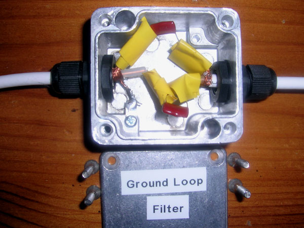
What's a two capacitor isolator look like?
Ok, so that's the technical description on how you build one. I'm not all that handy, pretty hopeless actually, but it only took me about 30minutes to put one together and it worked a treat completely eliminating my ground loop issues. I plugged it between the computer and antenna socket in the study. This blocked the low frequency 50Hz hum from travelling up the antenna cable thus removing the hum from the speakers in the family room. Below is a picture of the two capacitor isolator I built from parts I purchased at Jaycar for less than $10. The metal box provides shielding and the grommets remove any strain off the solder joints.